- Home
- > Cable
- > Special Cable
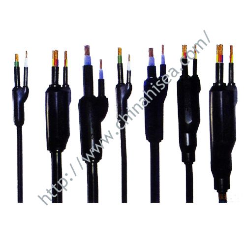
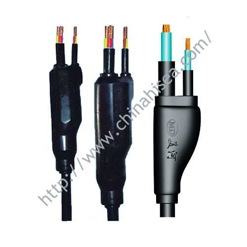
Prefabricated Branch Cable
Prefabricated Branch Cable
Safety in power supply
1 Trunk cable conductor without joint has good continuity and reduces trouble spots.
2 Branch joint made through whole course mechanical processing in the factory greatly reduces poor quality phenomena due to manmade factors.
3 Branch joint of rational structure and made through advanced LYZ workmanship has little contact resistance and cannot be affected by thermal expansion and cold shrinkage.
4 Pressing mould jacket processed in short time avoids variation of contact resistance owing to oxidization of copper core at the joint position which is exposed in the air for long time.
5 Branch joint has strict technical standard, inspection requirement, and quality control system as well.
Simpleness in installation, low requirement to environment, and convenience in construction
1 Small land-covering area facilitates effective use of floorage.
2 Low requirement to environment and low requirement to installation precision.
3 Simpleness in installation and low requirement to installation technology.The installation period is short only 1/10 or 1/20 of that of bus duct. The labor strength for installation is small.
4 Small bending radius greatly reduces installation difficulty and reduces space size.
Excellent shock resistance, air tightness, water proofing quality and flame resistance
1 Excellent shock resistance.Generally, the bus duct joint connected mechanically will be loose upon the wall is shocked. But GQFZ series prefabricated branch cable will not be affected. Especially passing through building sedimentation slots, no measure is need.
2 Excellent air tightness and water proofing quality. It can supply power normally in damp environment and be laid in the open air or underground.
3 NH type prefabricated branch cable can remain normal power supply operation for 90 min under flaming condition.
Free of maintenance
1 High once opening rate of prefabricated branch cable after being installed according to stipulated ways.
2 While normally work, prefabricated branch cable system is free of maintenance generally.
Prefabricated Branch Cable Model
|
Number
|
Name
|
Model
|
|||
|
Single Core
|
3 Cores Twisted type
|
4 Cores Twisted type
|
5 Cores Twisted type
|
||
|
1
|
PVC insulated andf sheathed prefabricated branch cable
|
FZ-VV
|
FZ-VV-3
|
FZ-VV-4
|
FZ-VV-5
|
|
2
|
PVC insulated andf sheathed flame retardant prefabricated branch cable
|
FZ-ZRVV
|
FZ-ZRVV-3
|
FZ-ZRVV-4
|
FZ-ZRVV-5
|
|
3
|
PVC insulated andf sheathed fireproof prefabricated branch cable
|
FZ-NHVV
|
FZ-NHVV-3
|
FZ-NHVV-4
|
FZ-NHVV-5
|
|
4
|
XLPE insulated PVC sheathed prefabricated branch cable
|
FZ-YJV
|
FZ-YJV-3
|
FZ-YJV-4
|
FZ-YJV-5
|
|
5
|
XLPE insulated PVC sheathed flame retardant prefabricated branch cable
|
FZ-ZRYJV
|
FZ-ZRYJV-3
|
FZ-ZRYJV-4
|
FZ-ZRYJV-5
|
|
6
|
XLPE insulated PVC sheathed fireproof prefabricated branch cable
|
FZ-NHYJV
|
FZ-NHYJV-3
|
FZ-NHYJV-4
|
FZ-NHYJV-5
|
Prefabricated Branch Cable Technical Parameter
|
Conductor
|
Insulation Thickness
mm
|
Sheath thickness
mm
|
Outer Diameter
mm
|
Weight
kg/km
|
A.C Test Voltage
kV/5Min.
|
20℃
Maximum DC resistance(Ω/km)
|
*1
40℃
ampacity
A
|
Impedance
Z Ω/km
|
Note
|
||||
|
Nominal
Cross-section
mm2
|
No.&Dia. or type No/mm
|
Dia.
mm
|
cosθ=1
|
cosθ=0.9
|
cosθ=0.8
|
Unbalanced load carrying capacity
(40 ℃)A
|
|||||||
|
6
10 |
7/1.04
7/1.35 |
3.1
3.7 |
0.7
0.7 |
1.4
1.4 |
8.0
8.5 |
105
150 |
3.5
3.5 |
3.08
1.83 |
61
85 |
3.93
2.33 |
3.61
2.17 |
3.25
1.96 |
58
80 |
|
16
25 35 50 70 |
Round tight
Pressure wire |
4.7
5.9 7.0 8.5 10.1 |
0.7 |
1.4
1.4 1.4 1.4 1.4 |
9.5
11.0 12.0 13.5 15.0 |
210
310 410 555 760 |
3.5
3.5 3.5 3.5 3.5 |
1.15
0.727 0.524 0.387 0.268 |
113
150 180 265 290 |
1.47
0.93 0.67 0.49 0.34 |
1.39
0.90 0.67 0.51 0.37 |
1.27
0.84 0.63 0.48 0.36 |
105
140 170 230 265 |
|
95
120 150 185 240 |
11.7
13.2 14.7 16.4 18.6 |
1.1
1.2 1.4 1.6 1.7 |
1.4
1.6 1.6 1.6 1.7 |
17.0
19.0 21.0 23.0 26.0 |
1020
1260 1570 1920 2470 |
3.5
3.5 3.5 3.5 3.5 |
0.193
0.153 0.124 0.0991 0.0754 |
345
405 460 530 640 |
0.25
0.20 0.16 0.13 0.10 |
0.28
0.24 0.20 0.18 0.15 |
0.28
0.24 0.21 0.19 0.16 |
325
380 435 500 595 |
|
|
300
400 500 600 |
20.8
24.1 26.9 30.2 |
1.8
2.0 2.2 2.4 |
1.8
2.0 2.2 2.4 |
29.0
32.0 36.0 40.0 |
3090
4080 5080 6390 |
3.5
3.5 3.5 3.5 |
0.0601
0.0470 0.0366 0.0283 |
725
845 970 1120 |
0.08
0.06 0.05 0.04 |
0.13
0.12 0.10 .09 |
0.15 |
685
795 920 1070 |
|
|
Conductor
|
Insulation Thickness
mm
|
Sheath Thickness
mm
|
O.D.
mm
|
Weight
kg/km
|
A.C Test Voltage
kV/5Min
|
20℃
Maximum DC resistance of (Ω/km)
|
*1
40℃Ampacity
A
|
Impedance Z Ω/km
|
Note
|
||||
|
Nominal Cross-section
mm2
|
No.&Dia. or Type
No/mm
|
Dia.
mm
|
cosθ=1
|
cosθ=0.9
|
cosθ=0.8
|
Unbalanced load carrying capacity
(40 ℃ )A
|
|||||||
|
6
10 |
7/1.04
7/1.35 |
3.1
3.7 |
0.7
0.7 |
1.4
1.4 |
19.3
20.5 |
430
620 |
3.5
3.5 |
3.14
1.87 |
53
72 |
4.01
2.38 |
3.68
2.21 |
3.31
2.00 |
45
61 |
|
16
25 35 50 70 |
Round tight
Pressure wire |
4.7
5.9 7.0 8.5 10.1 |
0.7 |
1.4
1.4 1.4 1.4 1.4 |
23.0
26.5 29.0 33.0 36.5 |
860
1270 1680 2270 3110 |
3.5
3.5 3.5 3.5 3.5 |
1.17
0.742 0.534 0.395 0.273 |
95
125 150 185 230 |
1.50
0.95 0.68 0.50 0.35 |
1.41
0.92 0.68 0.51 0.37 |
1.29
0.85 0.63 0.49 0.36 |
6814
105 130 160 205 |
|
95
120 150 185 240 |
11.7
13.2 14.7 16.4 18.6 |
1.1
1.2 1.4 1.6 1.7 |
1.4
1.6 1.6 1.6 1.7 |
41.0
46.0 51.0 55.5 63.0 |
4170
5150 6410 7840 10080 |
3.5
3.5 3.5 3.5 3.5 |
0.197
0.156 0.126 0.101 0.0769 |
280
325 380 440 535 |
0.25
0.20 0.16 0.13 0.10 |
0.28
0.24 0.20 0.17 0.15 |
0.28
0.24 0.21 0.18 0.16 |
250
290 335 385 455 |
|
|
300
400 500 600 |
20.8
24.1 26.9 30.2 |
1.8
2.0 2.2 2.4 |
1.8
2.0 2.2 2.4 |
70.0
77.5 87.0 96.5 |
12610
16650 20730 26080 |
3.5
3.5 3.5 3.5 |
0.0601
0.0470 0.0366 0.0283 |
625
735 865 1010 |
0.08
0.06 0.05 0.04 |
0.13
0.11 0.10 0.09 |
0.14 |
525
605 700 800 |
|
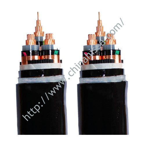
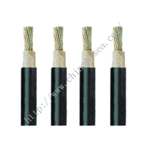
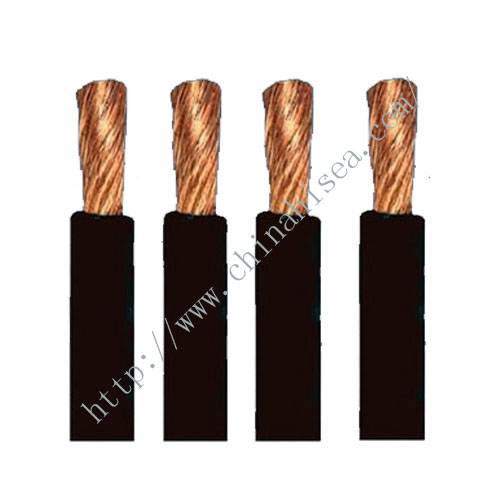
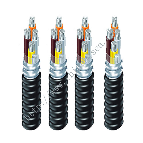
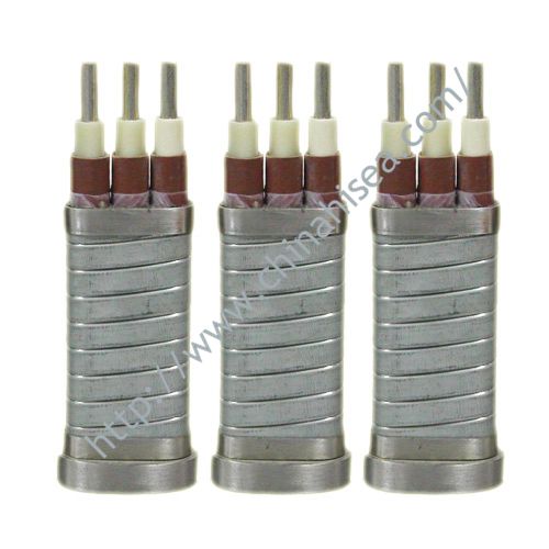
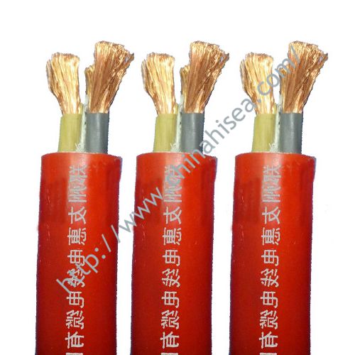
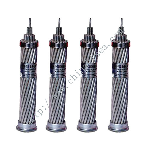
Prefabricated Branch Cable Show
Society certificates


CONTACT WITH US NOW