Steel Security Grille
Instruction:
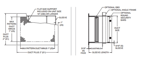
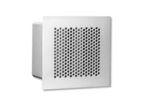
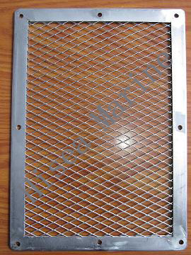
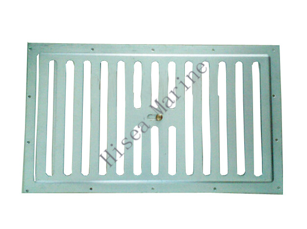
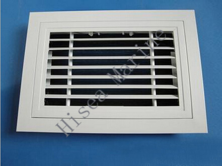
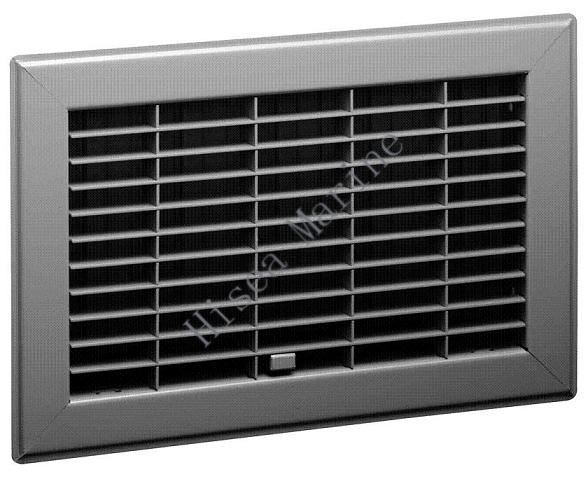
The series maximum security grilles feature a perforated face plate that makes finger penetration diffcult in areas that need a secure environment,The 46% free area perforation provides minimum pressure loss,making the grille an ideal choice for secure area that require large amouts of supply or return air.
Features:
1)3/16”Thick stitch welded sleeve(steel),1/8”Thick stitch welded sleeve(aluminum).
2)30”X30”maximum unit size.
3)6”,8”,10”,12”,14”,16” and 18” sleeve lengths.
Accessories:
1) Angel frame shipped loose and unpainted.(steel is constructed of 1 1/2”X1 1/2”X3/16” angle;aluminum is constructed of 1 1/2”X1 1/2”X1/8”angle)
2) Security bars on 6” center(steel is constructed of 3/4” diameter bars;aluminum is constructed of 1/2” diameter bars)
3) Anchor bars (steel is constructed of 3X3/4” diameter bars;aluminum is constructed of 3X1/2” diameter bars)
4) Two loose angle shipped loose and unpainted steel is constructed of 1 1/2”X1 1/2”X3/16” angle;aluminum is constructed of 1 1/2”X1 1/2”X1/8”angle)
5) Front or rear operated OBD
Finish:
Standard finish is british white
Optional finish is Mill
Drawing:
Refrence chart:
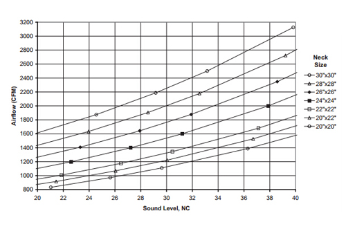
Dimensions:
|
IP data |
|
Metric data |
||||||||||
|
Nom |
Duct |
Neck |
Air |
Pt |
Throw |
Nom |
Duct |
Neck |
Air |
Pt |
Throw |
|
|
In |
ft² |
FPM |
CFM |
“WG |
ft |
mm |
m² |
m/s |
L/s |
Pa |
m |
|
|
X |
|
100 |
69 |
.005 |
1-3-8 |
- |
X |
|
0.51 |
33 |
1.2 |
0.5-1.0-2.4 |
|
150 |
104 |
.011 |
3-6-12 |
- |
0.76 |
49 |
2.8 |
1.0-1.8-3.6 |
||||
|
200 |
139 |
.020 |
5-8-16 |
- |
1.02 |
66 |
4.9 |
1.6-2.4-4.8 |
||||
|
250 |
174 |
.031 |
7-10-20 |
- |
1.27 |
82 |
7.7 |
2.0-3.0-6.0 |
||||
|
300 |
208 |
.044 |
8-12-22 |
15 |
1.52 |
98 |
11.0 |
2.4-3.6-6.8 |
||||
|
400 |
278 |
.079 |
11-16-26 |
24 |
2.03 |
131 |
19.6 |
3.2-4.8-7.9 |
||||
|
500 |
347 |
.123 |
13-20-29 |
30 |
2.54 |
164 |
30.6 |
4.0-6.0-8.8 |
||||
|
600 |
417 |
.177 |
16-22-32 |
36 |
3.05 |
197 |
44.1 |
4.8-6.8-9.7 |
||||
|
700 |
486 |
.241 |
19-24-34 |
40 |
3.56 |
229 |
60.0 |
5.6-7.4-10.4 |
||||
|
X 12” |
|
100 |
83 |
.005 |
2-4-9 |
- |
254
X |
0.077 |
0.51 |
39 |
1.2 |
0.5-1.1-2.6 |
|
150 |
125 |
.011 |
4-7-13 |
- |
0.76 |
59 |
2.8 |
1.1-2.0-4.0 |
||||
|
200 |
167 |
.020 |
6-9-17 |
- |
1.02 |
79 |
4.9 |
1.8-2.6-5.3 |
||||
|
250 |
208 |
.031 |
7-11-22 |
- |
1.27 |
98 |
7.7 |
2.2-3.3-6.6 |
||||
|
300 |
250 |
.044 |
9-13-25 |
16 |
1.52 |
118 |
11.0 |
2.6-4.0-7.5 |
||||
|
400 |
333 |
.079 |
12-17-28 |
24 |
2.03 |
157 |
19.6 |
3.5-5.3-8.6 |
||||
|
500 |
417 |
.123 |
15-22-32 |
31 |
2.54 |
197 |
30.6 |
4.4-6.6-9.7 |
||||
|
600 |
500 |
.177 |
17-25-35 |
37 |
3.05 |
236 |
44.1 |
5.3-7.5-10.6 |
||||
|
700 |
583 |
.241 |
20-27-38 |
41 |
3.56 |
275 |
60.0 |
6.2-8.1-11.4 |
||||
|
X 14” |
|
100 |
97 |
.005 |
2-4-9 |
- |
254
X |
0.090 |
0.51 |
46 |
1.2 |
0.5-1.2-2.9 |
|
150 |
146 |
.011 |
4-7-14 |
- |
0.76 |
69 |
2.8 |
1.2-2.1-4.3 |
||||
|
200 |
194 |
.020 |
6-9-19 |
- |
1.02 |
92 |
4.9 |
1.9-2.9-5.7 |
||||
|
250 |
243 |
.031 |
8-12-24 |
11 |
1.27 |
115 |
7.7 |
2.4-3.6-7.2 |
||||
|
300 |
292 |
.044 |
9-14-27 |
16 |
1.52 |
138 |
11.0 |
2.9-4.3-8.1 |
||||
|
400 |
389 |
.079 |
13-19-31 |
25 |
2.03 |
184 |
19.6 |
3.8-5.7-9.3 |
||||
|
500 |
486 |
.123 |
16-24-34 |
32 |
2.54 |
229 |
30.6 |
4.8-7.2-10.4 |
||||
|
600 |
583 |
.177 |
19-27-38 |
37 |
3.05 |
275 |
44.1 |
5.7-8.1-11.4 |
||||
|
700 |
681 |
.241 |
22-29-41 |
42 |
3.56 |
321 |
60.0 |
6.7-8.7-12.3 |
||||
|
IP data |
|
Metric data |
||||||||||
|
Nom |
Duct |
Neck |
Air |
Pt |
Throw |
Nom |
Duct |
Neck |
Air |
Pt |
Throw |
|
|
In |
ft² |
FPM |
CFM |
“WG |
ft |
mm |
m² |
m/s |
L/s |
Pa |
m |
|
|
12” X 12” |
1.000 |
100 |
100 |
.005 |
2-4-10 |
- |
305 X 305 |
0.093 |
0.51 |
47 |
1.2 |
0.5-1.2-2.9 |
|
150 |
150 |
.011 |
4-7-14 |
- |
0.76 |
71 |
2.8 |
1.2-2.2-4.4 |
||||
|
200 |
200 |
.020 |
6-10-19 |
- |
1.02 |
94 |
4.9 |
1.9-2.9-5.8 |
||||
|
250 |
250 |
.031 |
8-12-24 |
11 |
1.27 |
118 |
7.7 |
2.4-3.6-7.3 |
||||
|
300 |
300 |
.044 |
10-14-27 |
17 |
1.52 |
142 |
11.0 |
2.9-4.4-8.2 |
||||
|
400 |
400 |
.079 |
13-19-31 |
25 |
2.03 |
189 |
19.6 |
3.9-5.8-9.5 |
||||
|
500 |
500 |
.123 |
16-24-35 |
32 |
2.54 |
236 |
30.6 |
4.8-7.3-10.6 |
||||
|
600 |
600 |
.177 |
19-27-38 |
37 |
3.05 |
283 |
44.1 |
5.8-8.2-11.6 |
||||
|
700 |
700 |
.241 |
22-29-41 |
42 |
3.56 |
330 |
60.0 |
6.8-8.8-12.5 |
||||
|
12” X 14” |
1.167 |
100 |
117 |
.005 |
2-4-10 |
- |
305 X 356 |
0.108 |
0.51 |
55 |
1.2 |
0.6-1.3-3.1 |
|
150 |
175 |
.011 |
4-8-15 |
- |
0.76 |
83 |
2.8 |
1.3-2.4-4.7 |
||||
|
200 |
233 |
.020 |
7-10-21 |
- |
1.02 |
110 |
4.9 |
2.1-3.1-6.3 |
||||
|
250 |
292 |
.031 |
9-13-26 |
12 |
1.27 |
138 |
7.7 |
2.6-3.9-7.8 |
||||
|
300 |
350 |
.044 |
10-15-29 |
17 |
1.52 |
165 |
11.0 |
3.1-4.7-8.8 |
||||
|
400 |
467 |
.079 |
14-21-34 |
26 |
2.03 |
220 |
19.6 |
4.2-6.3-10.2 |
||||
|
500 |
583 |
.123 |
17-26-38 |
33 |
2.54 |
275 |
30.6 |
5.2-7.8-11.4 |
||||
|
600 |
700 |
.177 |
21-29-41 |
38 |
3.05 |
330 |
44.1 |
6.3-8.8-12.5 |
||||
|
700 |
817 |
.241 |
24-31-44 |
43 |
3.56 |
385 |
60.0 |
7.3-9.6-13.5 |
||||
|
12” X 16” |
1.333 |
100 |
133 |
.005 |
2-5-11 |
- |
305 X 406 |
0.124 |
0.51 |
63 |
1.2 |
0.6-1.4-3.4 |
|
150 |
200 |
.011 |
5-8-17 |
- |
0.76 |
94 |
2.8 |
1.4-2.5-5.0 |
||||
|
200 |
267 |
.020 |
7-11-22 |
- |
1.02 |
126 |
4.9 |
2.2-3.4-6.7 |
||||
|
250 |
333 |
.031 |
9-14-28 |
12 |
1.27 |
157 |
7.7 |
2.8-4.2-8.4 |
||||
|
300 |
400 |
.044 |
11-17-31 |
18 |
1.52 |
189 |
11.0 |
3.4-5.0-9.5 |
||||
|
400 |
533 |
.079 |
15-22-36 |
26 |
2.03 |
252 |
19.6 |
4.5-6.7-10.9 |
||||
|
500 |
667 |
.123 |
18-28-40 |
33 |
2.54 |
315 |
30.6 |
5.6-8.4-12.2 |
||||
|
600 |
800 |
.177 |
22-31-44 |
39 |
3.05 |
378 |
44.1 |
6.7-9.5-13.4 |
||||
|
700 |
933 |
.241 |
26-34-48 |
43 |
3.56 |
440 |
60.0 |
7.8-10.2-14.4 |
||||
|
IP data |
|
Metric data |
||||||||||
|
Nom |
Duct |
Neck |
Air |
Pt |
Throw |
Nom |
Duct |
Neck |
Air |
Pt |
Throw |
|
|
In |
ft² |
FPM |
CFM |
“WG |
ft |
mm |
m² |
m/s |
L/s |
Pa |
m |
|
|
14” X 14” |
1.361 |
100 |
136 |
.005 |
2-5-11 |
- |
356 X 356 |
0.126 |
0.51 |
64 |
1.2 |
0.6-1.4-3.4 |
|
150 |
204 |
.011 |
5-8-17 |
- |
0.76 |
96 |
2.8 |
1.4-2.5-5.1 |
||||
|
200 |
272 |
.020 |
7-11-22 |
- |
1.02 |
128 |
4.9 |
2.3-3.4-6.8 |
||||
|
250 |
340 |
.031 |
9-14-28 |
12 |
1.27 |
161 |
7.7 |
2.8-4.2-8.5 |
||||
|
300 |
408 |
.044 |
11-17-31 |
18 |
1.52 |
193 |
11.0 |
3.4-5.1-9.6 |
||||
|
400 |
544 |
.079 |
15-22-36 |
27 |
2.03 |
257 |
19.6 |
4.5-6.8-11.0 |
||||
|
500 |
681 |
.123 |
19-28-41 |
33 |
2.54 |
321 |
30.6 |
5.6-8.5-12.3 |
||||
|
600 |
817 |
.177 |
22-31-44 |
39 |
3.05 |
385 |
44.1 |
6.8-9.6-13.5 |
||||
|
700 |
953 |
.241 |
26-34-48 |
43 |
3.56 |
450 |
60.0 |
7.9-10.3-14.6 |
||||
|
14” X 16” |
1.556 |
100 |
156 |
.005 |
2-5-12 |
- |
356 X 406 |
0.145 |
0.51 |
73 |
1.2 |
0.7-1.5-3.6 |
|
150 |
233 |
.011 |
5-9-18 |
- |
0.76 |
110 |
2.8 |
1.5-2.7-5.4 |
||||
|
200 |
311 |
.020 |
8-12-24 |
- |
1.02 |
147 |
4.9 |
2.4-3.6-7.2 |
||||
|
250 |
389 |
.031 |
10-15-30 |
13 |
1.27 |
184 |
7.7 |
3.0-4.5-9.0 |
||||
|
300 |
467 |
.044 |
12-18-34 |
19 |
1.52 |
220 |
11.0 |
3.6-5.4-10.2 |
||||
|
400 |
622 |
.079 |
16-24-39 |
27 |
2.03 |
294 |
19.6 |
4.8-7.2-11.8 |
||||
|
500 |
778 |
.123 |
20-30-43 |
34 |
2.54 |
367 |
30.6 |
6.0-9.0-13.2 |
||||
|
600 |
933 |
.177 |
24-34-48 |
39 |
3.05 |
440 |
44.1 |
7.2-10.2-14.4 |
||||
|
700 |
1089 |
.241 |
28-36-51 |
44 |
3.56 |
514 |
60.0 |
8.4-11.0-15.6 |
||||
|
14” X 18” |
1.750 |
100 |
175 |
.005 |
2-5-13 |
- |
356 X 457 |
0.163 |
0.51 |
83 |
1.2 |
0.7-1.6-3.8 |
|
150 |
263 |
.011 |
5-9-18 |
- |
0.76 |
124 |
2.8 |
1.6-2.9-5.8 |
||||
|
200 |
350 |
.020 |
8-13-25 |
- |
1.02 |
165 |
4.9 |
2.6-3.8-7.7 |
||||
|
250 |
438 |
.031 |
11-16-32 |
14 |
1.27 |
206 |
7.7 |
3.2-4.8-9.6 |
||||
|
300 |
525 |
.044 |
13-19-36 |
19 |
1.52 |
248 |
11.0 |
3.8-5.8-10.8 |
||||
|
400 |
700 |
.079 |
17-25-41 |
28 |
2.03 |
330 |
19.6 |
5.1-7.7-12.5 |
||||
|
500 |
875 |
.123 |
21-32-46 |
34 |
2.54 |
413 |
30.6 |
6.4-9.6-14.0 |
||||
|
600 |
1050 |
.177 |
25-36-50 |
40 |
3.05 |
496 |
44.1 |
7.7-10.8-15.3 |
||||
|
700 |
1225 |
.241 |
29-39-54 |
44 |
3.56 |
578 |
60.0 |
9.0-11.7-16.6 |
||||
|
IP data |
|
Metric data |
||||||||||
|
Nom |
Duct |
Neck |
Air |
Pt |
Throw |
Nom |
Duct |
Neck |
Air |
Pt |
Throw |
|
|
In |
ft² |
FPM |
CFM |
“WG |
ft |
mm |
m² |
m/s |
L/s |
Pa |
m |
|
|
X |
1.778 |
100 |
178 |
.005 |
2-5-13 |
- |
406 X 406 |
0.165 |
0.51 |
84 |
1.2 |
0.7-1.6-3.9 |
|
150 |
267 |
.011 |
5-10-19 |
- |
0.76 |
126 |
2.8 |
1.6-2.9-5.8 |
||||
|
200 |
356 |
.020 |
8-13-25 |
- |
1.02 |
168 |
4.9 |
2.6-3.8-7.7 |
||||
|
250 |
444 |
.031 |
11-16-32 |
14 |
1.27 |
210 |
7.7 |
3.2-4.8-9.6 |
||||
|
300 |
533 |
.044 |
13-19-36 |
19 |
1.52 |
252 |
11.0 |
3.8-5.8-10.8 |
||||
|
400 |
711 |
.079 |
17-25-41 |
28 |
2.03 |
336 |
19.6 |
5.1-7.7-12.5 |
||||
|
500 |
889 |
.123 |
21-32-46 |
34 |
2.54 |
420 |
30.6 |
6.4-9.6-14.0 |
||||
|
600 |
1067 |
.177 |
25-36-50 |
40 |
3.05 |
503 |
44.1 |
7.7-10.8-15.3 |
||||
|
700 |
1244 |
.241 |
29-39-54 |
44 |
3.56 |
587 |
60.0 |
9.0-11.7-16.6 |
||||
|
16”
X |
2.222 |
100 |
222 |
.005 |
3-6-14 |
- |
406 X 508
|
0.206 |
0.51 |
105 |
1.2 |
0.8-1.8-4.3 |
|
150 |
333 |
.011 |
6-11-21 |
- |
0.76 |
157 |
2.8 |
1.8-3.2-6.5 |
||||
|
200 |
444 |
.020 |
9-14-28 |
- |
1.02 |
210 |
4.9 |
2.9-4.3-8.7 |
||||
|
250 |
556 |
.031 |
12-18-36 |
15 |
1.27 |
262 |
7.7 |
3.6-5.4-10.8 |
||||
|
300 |
667 |
.044 |
14-21-40 |
20 |
1.52 |
315 |
11.0 |
4.3-6.5-12.2 |
||||
|
400 |
889 |
.079 |
19-28-46 |
29 |
2.03 |
420 |
19.6 |
5.8-8.7-14.1 |
||||
|
500 |
1111 |
.123 |
24-36-52 |
35 |
2.54 |
524 |
30.6 |
7.2-10.8-15.8 |
||||
|
600 |
1333 |
.177 |
28-40-57 |
41 |
3.05 |
629 |
44.1 |
8.7-12.2-17.3 |
||||
|
700 |
1556 |
.241 |
33-43-61 |
45 |
3.56 |
734 |
60.0 |
10.1-13.2-18.7 |
||||
|
16”
X |
2.444 |
100 |
244 |
.005 |
3-6-15 |
- |
406 X 559 |
0.227 |
0.51 |
115 |
1.2 |
0.9-1.9-4.5 |
|
150 |
367 |
.011 |
6-11-22 |
- |
0.76 |
173 |
2.8 |
1.9-3.4-6.8 |
||||
|
200 |
489 |
.020 |
10-15-30 |
- |
1.02 |
231 |
4.9 |
3.0-4.5-9.1 |
||||
|
250 |
611 |
.031 |
12-19-37 |
15 |
1.27 |
288 |
7.7 |
3.8-5.7-11.3 |
||||
|
300 |
733 |
.044 |
15-22-42 |
20 |
1.52 |
346 |
11.0 |
4.5-6.8-12.8 |
||||
|
400 |
978 |
.079 |
20-30-49 |
29 |
2.03 |
461 |
19.6 |
6.1-9.1-14.8 |
||||
|
500 |
1222 |
.123 |
25-37-54 |
36 |
2.54 |
577 |
30.6 |
7.6-11.3-16.5 |
||||
|
600 |
1467 |
.177 |
30-42-60 |
41 |
3.05 |
692 |
44.1 |
9.1-12.1-18.1 |
||||
|
700 |
1711 |
.241 |
35-46-64 |
46 |
3.56 |
808 |
60.0 |
10.6-13.8-19.6 |
||||
|
IP data |
|
Metric data |
||||||||||
|
Nom |
Duct |
Neck |
Air |
Pt |
Throw |
Nom |
Duct |
Neck |
Air |
Pt |
Throw |
|
|
In |
ft² |
FPM |
CFM |
“WG |
ft |
mm |
m² |
m/s |
L/s |
Pa |
m |
|
|
18” X 20” |
2.500 |
100 |
250 |
.005 |
3-6-15 |
- |
457 X 508 |
0.232 |
0.51 |
118 |
1.2 |
0.9-1.9-4.6 |
|
150 |
375 |
.011 |
6-11-23 |
- |
0.76 |
177 |
2.8 |
1.9-3.4-6.9 |
||||
|
200 |
500 |
.020 |
10-15-30 |
- |
1.02 |
236 |
4.9 |
3.1-4.6-9.2 |
||||
|
250 |
625 |
.031 |
13-19-38 |
15 |
1.27 |
295 |
7.7 |
3.8-5.7-11.5 |
||||
|
300 |
750 |
.044 |
15-23-43 |
21 |
1.52 |
354 |
11.0 |
4.6-6.9-13.0 |
||||
|
400 |
875 |
.079 |
18-26-46 |
25 |
2.03 |
413 |
19.6 |
5.4-8.0-14.0 |
||||
|
500 |
1000 |
.123 |
20-30-49 |
29 |
2.54 |
472 |
30.6 |
6.1-9.2-15.0 |
||||
|
600 |
1250 |
.177 |
25-38-55 |
36 |
3.05 |
590 |
44.1 |
7.6-11.5-16.7 |
||||
|
700 |
1500 |
.241 |
30-43-60 |
41 |
3.56 |
708 |
60.0 |
9.2-13-18.3 |
||||
Steel Security Grille:
Society certificates


CONTACT WITH US NOW