- Home
- > Cable
- > Marine Cable
RFOU Flame retardant Mud resistant offshore power cable
RFOU P1/P8 Halogen free flame retardant mud resistant mud resistant offshore power cable
RFOU P1/P8 Halogen free flame retardant mud resistant offshore power cable application
This cable is mainly intended for power,lighting,control system of offshore units,meets the mud resistant requirements of NEK 606.
RFOU P1/P8 Halogen free flame retardant mud resistant offshore power cable standards
Design IEC 60092-353
Conductor IEC 60228
Insulation IEC 60092-351
Sheath IEC 60092-359
Flame retardant IEC 60332-3
Halogen free:IEC 60754
Low smoke:IEC 60134
Mud resistant:NEK 606
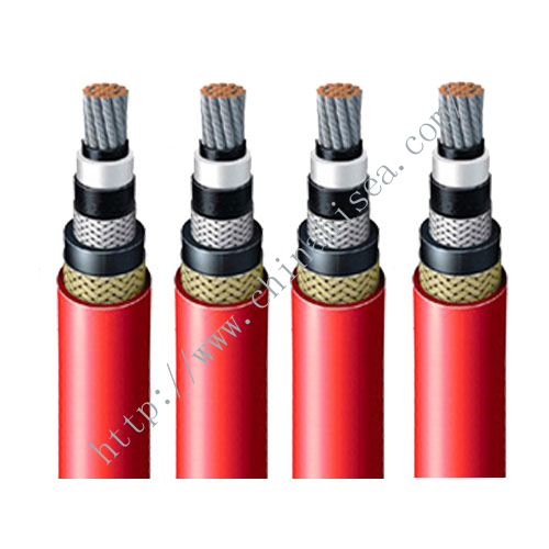
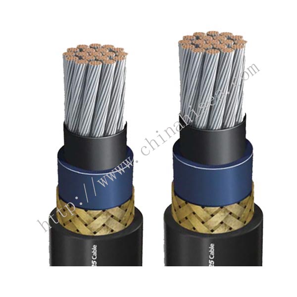
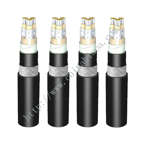
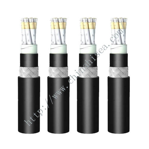
RFOU P1/P8 Halogen free flame retardant mud resistant offshore power cable structure
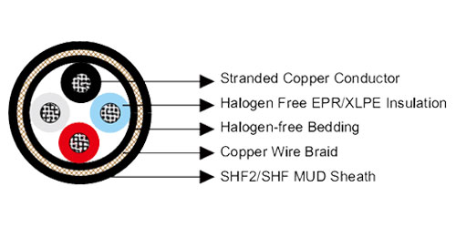
1. Conductor stranded tinned cooper Class 2
2. EPR insulated
3. Halogen free compound filler
4. Polyolefin inner covering
5. Tinned copper wire braid
6. Flame retardant and halogen free mud resistant thermoset compund,SHF2 outer sheath
7. Outer sheath color: Black
RFOU P1/P8 Halogen free flame retardant mud resistant offshore power cable Main Parameter
Maximum conductor temperature:+90℃
Rated Voltage:0.6/1kv
Tested Voltage:3.5kv/5min
Flame spread test on bunched cable:Category A
Smoke density of finished cable:≥60%
Bending radius : 8 × OD ( installing ); 6 × OD ( fixed installation )RFOU P1/P8 Halogen free flame retardant mud resistant offshore power cable Technical specification
| Nominal Conductor Cross-Section Area | mm2 | 1.5 | 2.5 | 4 | 6 | 10 | 16 | 25 | 35 | 50 | 70 |
| Nominal Conductor Diameter | mm | 1.6 | 2.1 | 2.6 | 3.2 | 4.0 | 5.1 | 6.5 | 7.4 | 8.7 | 10.3 |
| Max. D.C. Resistance @20℃ | Ω/km | 12.2 | 7.56 | 4.7 | 3.11 | 1.84 | 1.16 | 0.734 | 0.529 | 0.391 | 0.27 |
| Continuous rated current @45℃1Core | A | 23 | 30 | 40 | 52 | 72 | 96 | 127 | 157 | 196 | 242 |
| Continuous rated current @45℃2Core | A | 20 | 26 | 34 | 44 | 61 | 82 | 108 | 133 | 167 | 206 |
| Continuous rated current @45℃3&4Core | A | 16 | 21 | 28 | 36 | 50 | 67 | 89 | 110 | 137 | 169 |
| Short Circuit Current 1s | A | 210 | 360 | 570 | 860 | 1430 | 2290 | 3580 | 5010 | 7150 | 10020 |
| Working Voltage | KV | 0.6/1 | 0.6/1 | 0.6/1 | 0.6/1 | 0.6/1 | 0.6/1 | 0.6/1 | 0.6/1 | 0.6/1 | 0.6/1 |
| Nominal Conductor Cross-Section Area | mm2 | 95 | 120 | 150 | 185 | 240 | 300 | 400 | 500 | 630 |
| Nominal Conductor Diameter | mm | 12.2 | 13.8 | 15.1 | 17.0 | 19.6 | 21.9 | 24.6 | 27.6 | 32.5 |
| Max. D.C Resistance @20℃ | Ω/km | 0.195 | 0.154 | 0.126 | 0.1 | 0.0762 | 0.0607 | 0.0475 | 0.0369 | 0.0286 |
| Continuous rated current @45℃1Core | A | 293 | 339 | 389 | 444 | 522 | 601 | 690 | 780 | 890 |
| Continuous rated current @45℃2Core | A | 249 | 288 | 331 | 444 | 444 | 511 | 587 | 663 | 757 |
| Continuous rated current @45℃3&4Core | A | 205 | 237 | 272 | 311 | 365 | 421 | 483 | 546 | 623 |
| Short Circuit Current 1s | A | 13590 | 17170 | 21460 | 26470 | 34340 | 42930 | 57230 | 71540 | 90140 |
| Working Voltage | KV | 0.6/1 | 0.6/1 | 0.6/1 | 0.6/1 | 0.6/1 | 0.6/1 | 0.6/1 | 0.6/1 | 0.6/1 |
Ambient temperature correction factor
| Ambient temperature correction factor |
35
|
40
|
45
|
50
|
55
|
60
|
65
|
70
|
75
|
80
|
|||||
| Rated Factor |
1.1
|
1.05
|
1.0
|
0.94
|
0.88
|
0.82
|
0.74
|
0.67
|
0.58
|
0.47
|
|||||
RFOU P1/P8 Halogen free flame retardant mud resistant offshore power cable Show
Society certificates


CONTACT WITH US NOW