
- Home
- > Cable
- > General Cable

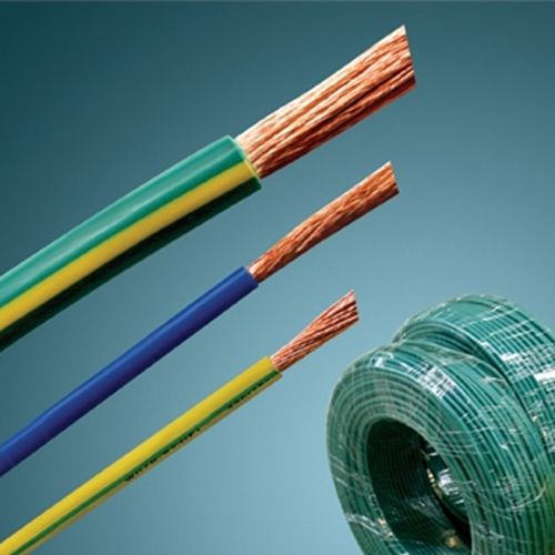
crosslinked polyolefin insulated wire
Cross-linked polyolefin insulated wire description
Cross-linking polyolefins insulated cable (wire) has the advantages of excellent mechanical and physical properties, excellent electrical properties. It is used in such places as electrical appliance, instrument and telecom device with A.C.rated voltage U0/U up to and including 450/750V.
The main features of the flame retardant cable is hard to get fire or that the continuous burning of cables is very limited when it is on fire. It applies to the places necessary to resist fire.
Fire-resistance of cable can operate normally for some time when it is burning except that it can transmit electrical power under normal condition. It is used in the places necessary to resist fire.
The main characteristics of low smoke, halogen-free, flame when it is burning cable &wire is very low smoke emission and harmless (low toxic, low corrosive) besides the property of flame retardant. It can be used in the places with special demands of property of flame retardant, the density of smoke emission and toxic index when cable gets burning such as subway, tunnel, nuclear power station.
Cross-linked polyolefin insulated wire Standards
The cable is manufactured in accordance with out enterprise standard.It can also be produced according to special requirements put forward by clients.
The flame retardant property of the flame retardant cable must meet the corresponding demands of class A, B, or C, which is, stipulated in GB/T 18380.3-2001.Amongst the 3 classes, class A is best C worst. Clients can select any type of cable as practical needs.
Fire-resistance property of the fire-resistance cable can be classified as class A(9500C—10000C/90min)and class B(7500C—8000C/90min.) In accordance with the standard of GB 12666.6.6 Clients can choose any type cable as practical needs.
The flame retardant property of low smoke, halogen-free, flame retardant cable must the corresponding requirements of class A,B or C which is stipulated in GB/T 18380.3—2001. It must pass the test of smoke density described in GB/T 17651—1998, and the test measuring the pH vault and conductivity which is stipulated in GB/T 17650.2—1998.
Cross-linked polyolefin insulated wire Model
Type of the common cable:
| Model | Name |
| BYJ | copper conductor cross linking polyolefins insulated cable (wire) |
| BYJR | copper conductor cross linking polyolefins insulated flexible cable |
| BYJV | copper conductor cross linking polyolefins insulated PVC sheathed round cable |
| BYJVB | copper conductor cross linking polyolrfins insulated PVC sheathed flat cable(wire) |
Plus ZA、ZB、ZC before the type of common cable
Type of the fire resistance cable:
Plus N before the type of common cable
Type of the low smoke, halogen-free, flame retardant cable:
| Model | Name |
| WDZ—BYJ |
copper conductor cross linkingpolyoefins insulated haloen-free flame retardant cable wired |
| WDZ—BYR | copper conductor cross linkingpolyolefins insulated haloen-free flame retardant flexible cable |
| WDZ—BYJY | copper conductor cross linking polyolefins insulated, flame retardant polyolefins sheathed halogen-free round cable |
| WDZ—BYJYB | copper conductor cross linking polyolefins insulated, flame retardant polyolefins sheathed halogen-free flat cable (wire) |
Cross-linked polyolefin insulated wire Service Condition
Rated voltage U0/U is 450/750 and 300/500 volts.Permissible continuous working temperature of cable conductor is 90℃.
Ambient temperature is not lower than 0℃ and its minimum bending radius is as follows when cable is installed:
—for O.D. less than 25 millimeter equal to or greater than 4 times O.D.
—for O.D. not less than 25 millimeter, equal to or greater than 6 time O.D.
Cross-linked polyolefin insulated wire Technical Parameter
BYJ (FBYJ), ZR(C)-BYJ 300/500V
|
Nominal Area |
Conductor Category |
Refer Outer Diameter |
Refer Weight |
20 ℃ Maximum DC resistance of conductor Ω/km |
Approximate Ampacity |
|
0.5 0.75 0.75 1.0 1.0 |
1 1 2 1 2 |
1.9 2.0 2.2 2.2 2.3 |
7 9 10 12 12 |
36.0 24.5 24.5 18.1 18.1 |
16 20 20 24 24 |
BYJ (FBYJ), ZR(C)-BYJ 450/750V
|
Nominal Area |
Conductor Category |
Refer Outer Diameter |
Refer Weight |
20 ℃ Maximum DC resistance of conductor Ω/km |
Approximate Ampacity |
|
1.5 1.5 2.5 2.5 4 4 6 6 10 16 25 35 50 70 95 120 150 185 240 300 400 |
1 2 1 2 1 2 1 2 2 2 2 2 2 2 2 2 2 2 2 2 2 |
2.6 2.8 3.3 3.5 3.7 4.0 4.2 4.6 5.6 7.0 8.5 9.6 11.7 13.1 15.4 17.2 19.0 21.3 24.5 27.1 30.7 |
17 18 28 29 42 44 62 63 103 163 254 348 473 672 931 1168 1438 1803 2367 2964 3784 |
12.1 12.1 7.41 7.41 4.61 4.61 3.08 3.08 1.83 1.15 0.727 0.524 0.387 0.268 0.193 0.153 0.124 0.0991 0.0754 0.0601 0.0470 |
33 33 42 43 56 55 77 77 103 140 171 212 269 335 392 444 503 580 673 785 941 |
BYJ (FBYJ), ZR(C)-BYJR 450/750V
|
Nominal Area |
Refer Outer Diameter |
Refer Weight |
20 ℃ Maximum DC resistance of conductor Ω/km |
Approximate Ampacity |
|
2.5 4 6 10 16 25 35 50 70 |
3.5 4.1 4.7 6.5 7.5 9.6 10.7 12.6 14.7 |
29 44 65 113 169 269 359 495 683 |
7.41 4.61 3.08 1.83 1.15 0.727 0.524 0.387 0.268 |
42 55 77 103 140 171 212 269 335 |
BYJ (FBYJ), ZR(C)-BYJR 450/750V
|
Nominal Area |
Refer Outer Diameter |
Refer Weight |
20 ℃ Maximum DC resistance of conductor Ω/km |
Approximate Ampacity |
|
1×0.75 1×1.0 1×1.5 1×2.5 1×4 1×6 1×10 |
3.6 3.8 4.2 4.6 5.3 6.0 7.3 |
19 20 29 40 58 81 127 |
24.5 18.1 12.1 7.41 4.61 3.08 1.83 |
19 24 33 42 54 75 100 |
|
2×1.5 2×2.5 2×4. 2×6 2×10 2×16 2×25 2×35 |
8.5 9.3 10.2 11.7 14.9 17.1 20.9 24.0 |
98 129 171 234 387 551 843 1139 |
12.1 7.41 4.61 3.08 1.83 1.15 0.727 0.524 |
26 36 47 67 90 122 140 170 |
|
3×1.5 3×2.5 3×4. 3×6 3×10 3×16 3×25 3×35 |
9.0 9.8 10.8 12.7 15.8 18.2 22.6 25.4 |
120 156 213 306 487 703 1103 1470 |
12.1 7.41 4.61 3.08 1.83 1.15 0.727 0.524 |
22 30 38 49 66 87 118 144 |
BYJV(FBYJV),ZR(C)-BYJV 300/500V
|
Nominal Area |
Refer Outer Diameter |
Refer Weight |
20 ℃ Maximum DC resistance of conductor Ω/km |
Approximate Ampacity |
|
4×1.5 4×2.5 4×4 4×6 4×10 4×16 4×25 4×35 |
9.6 10.5 12.1 14.2 17.2 20.3 25.1 27.9 |
139 190 273 392 607 903 1413 1860 |
12.1 7.41 4.61 3.08 1.83 1.15 0.727 0.524 |
23 31 38 50 67 89 118 145 |
|
5×1.5 5×2.5 5×4 5×6 5×10 5×16 5×25 5×35 |
10.3 11.4 13.5 15.4 18.7 22.5 27.5 31.0 |
165 228 339 473 737 1120 1725 2306 |
12.1 7.41 4.61 3.08 1.83 1.15 0.727 0.524 |
23 31 39 49 66 88 119 143 |
BYJVB(FBYJVB),ZR(C)-BYJVB 300/500V
|
Nominal Area |
Refer Outer Diameter |
Refer Weight |
20 ℃ Maximum DC resistance of conductor Ω/km |
Approximate Ampacity |
|
2×0.75 2×1.0 2×1.5 2×2.5 2×4 2×6 2×10 |
3.9×5.9 4.1×6.3 4.5×7.2 5.1×8.2 5.9×9.7 6.9×11.5 8.0×13.4 |
37 39 59 84 124 178 272 |
24.5 18.1 12.1 7.41 4.61 3.08 1.83 |
17 22 26 36 47 67 90 |
|
3×0.75 3×1.0 3×1.5 3×2.5 3×4 3×6 3×10 |
3.9×8.0 4.1×8.4 4.5×9.8 5.1×11.2 5.9×13.7 6.9×16.1 8.0×18.9 |
53 56 86 123 187 263 403 |
24.5 18.1 12.1 7.41 4.61 3.08 1.83 |
17 21 22 30 38 49 66 |
Cross-linked polyolefin insulated wire show
Related products for "crosslinked polyolefin insulated wire"
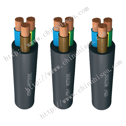 VDE H05RN-F/H05RNH2-F Power Cable
 AS Standards Fire Resistant Cable
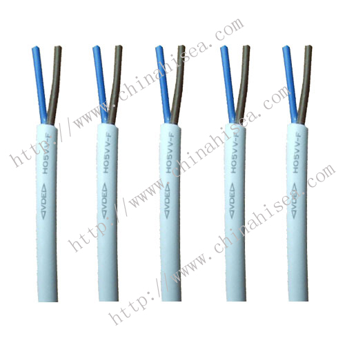 VDE H05VV-F/H05VVH2-F Power wire
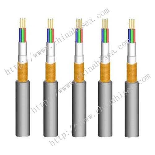 PVC insulated Braided Shield Flexible Cable
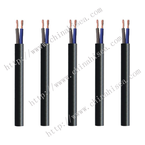 Light PVC sheathed Flexible Cable
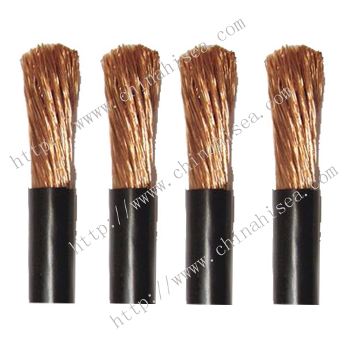 PVC insulated Flexible wire
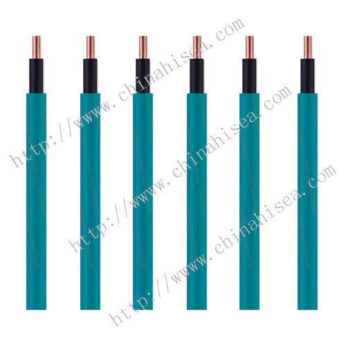 Light PVC sheathed cable
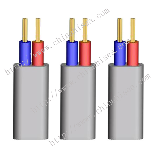 PVC insulated and sheathed Flexible Flat Cable
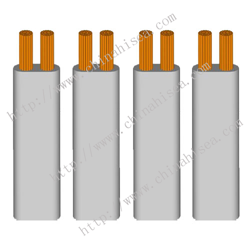 PVC insulated Flat Flexible Cable
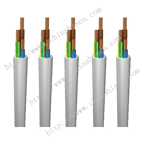 VDE H05BN4-F Power cable
Society certificates


CONTACT WITH US NOW